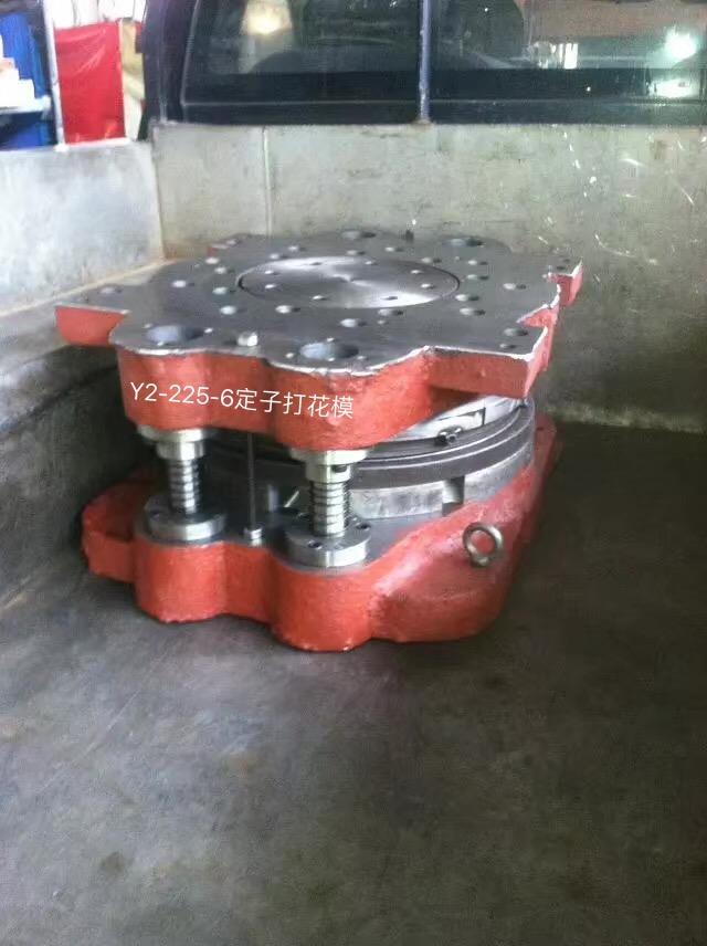
For the composite mold industry, there are too many factors affecting its development and manufacturing. The following is an analysis of its structural elements:
1. Cavity layout.
Confirm the number of cavities and how to place them according to the geometrical characteristics of the plastic parts, the requirements of scale accuracy, the size of the batch, the difficulty of mold manufacturing, and the cost of the mold.
Regarding injection molds, the precision of plastic parts is grades 3 and 3a, and the weight is 5 grams. The hardened casting system is used, and the number of cavities is 4-6. The plastic parts are of general precision (grade 4-5). The data is local crystallization data. The number of cavities can be 16-20; the number of cavities for plastic parts is 12-16 grams; the number of cavities is 8-12; the number of cavities for plastic parts is 50-100 grams. 4-8.
For amorphous plastic parts, the recommended number of cavities is 24-48, 16-32 and 6-10. When adding plastic parts continuously, multi-cavity molds are rarely used. 7-9 grade precision plastic parts, the number of multi-cavity increased to 50% compared with the 4-5 grade precision plastic.
2. Select the ejection method (ejector, ejector, push plate, combined ejection), determine the undercut processing method, and pull the core.
3. Confirm the structure of the primary molding parts and structural parts.
4. Confirm the gating system (the shape, orientation, and size of the main runner, the runner, and the gate) and the exhaust system (the method of exhaust, the orientation of the exhaust tank, and the size).
5. Confirm the parting surface.
The orientation of the parting surface should be conducive to mold processing, exhaust, demolding and molding operations, and the surface quality of plastic parts.
6. Determine the shape and orientation of the cooling and heating methods and heating and cooling grooves, and the location of the heating element. 6. According to the mold information, strength calculations, or empirical data, confirm the thickness and external dimensions of the mold parts, the external structure, and the orientation of all connections, positioning, and guides.
7. Considering the strength of each part of the mold, calculate the operating dimensions of the molded part. If these problems are dealt with, the structure of the mold will be dealt with naturally. At this time, you should start to sketch the mold structure to prepare for the formal drawing.

Related News
- High-voltage motor punching die operation specification
- What are the components of a simple stamping blanking mold?
- Blanking die process and principle
- Using method of rotor casting aluminum mold
- Possible problems with rotor molds
- Precautions in the use of self-service die
- Characteristics of stator mold
- Tips for self-help die
- Introduction of blanking die
- Attentions in the design of fixed-rotor tooling fixtures
- Precautions for the use of stator embossing molds


