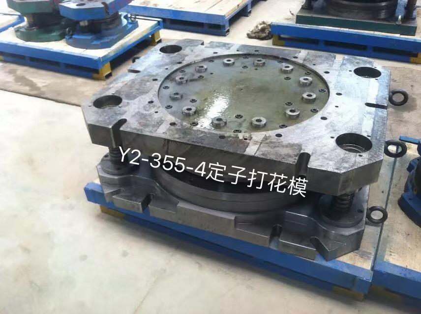
Simple blanking die , which consists of two parts: upper die and lower die. The upper mold includes the upper template and all the components mounted on it, and the lower mold includes the lower template and all the components mounted on it. When the die is installed on the press, the die handle of the upper die is clamped in the die handle hole of the slider of the press, moves up and down together with the slider, and is fixed on the work surface of the press by screws and pressure plates. Its operating principle is as follows. Before the die is punched, the strip is fed against the two guide pins until it touches the guide pin on one side. When punching, the discharge plate first presses the material, and then the punch is punched. The punched workpiece leaks from the hole of the die. When the upper mold is raised, the waste material is unloaded from the punch by the elastic force of the compression rubber. The second and subsequent feedings are positioned by the blocking pin, and punched at an interval. After punching the bar, turn it 180 degrees, and then punch the dotted line in the layout chart. The die structure consists of the following five parts.
Simple stamping blanking die structure diagram
①Working parts
Complete material parts for punching dies, including male and female dies.
② Positioning parts
It is the part that determines the correct position of the strip in the die. The guide pin plays a guiding role in the feeding of the material. When the strip deviates from the guide pin, it will punch out the missing scrap. The stopper pin restricts the position where the bar feeds. Cross-cutting, after the first punching, leave a position to flip the strip 180 degrees and punch back, so the distance from the blocking pin to the edge of the die hole is one workpiece width plus two overlapping edges, so that after the strip is flipped Stamping positioning.
③Unloading and pushing parts
After the workpiece is punched from the strip, due to the elastic recovery of the material, the workpiece is stuck in the cavity of the die, and the strip is stuck on the punch. You need to remove them to ensure the smooth operation of the stamping. The waste strip exits the punch, which is a discharging device composed of a discharging plate, rubber, and screws, which uses the discharging force generated by the compression rubber (or spring) to complete. The workpieces stuck in the cavity of the die are pushed from the cavity of the die one by one when the punch is pressed.
④Guide members
The parts that guarantee the correct movement of the upper mold to the lower mold. The guide post of the press on the lower template and the guide sleeve of the device on the upper template form the guide device of the upper and lower molds to ensure that the gap between the convex mold and the concave mold is uniform, which is conducive to improving the quality of the stamping part.
⑤ connecting parts
It is a component that fixes the male and female molds to the upper and lower molds, and fixes the upper and lower molds to the press. The male die is fixed to the upper template by a fixing plate, and the female die is directly fixed to the lower template. They are fixed with screws, tightened, and positioned with pins. The backing plate is used to support the punching pressure of the punch to protect the plane of the upper template from being pushed out of the pit. The typical structure of a stamping die is composed of the above five parts, but not all the die structures have these five parts. The structure of the die depends on the requirements of the workpiece, production batch, production conditions and molding conditions. Therefore, to be familiar with various die structures, you must personally participate in production practice.

Related News
- High-voltage motor punching die operation specification
- Blanking die process and principle
- Using method of rotor casting aluminum mold
- Structural factors affecting composite molds
- Possible problems with rotor molds
- Precautions in the use of self-service die
- Characteristics of stator mold
- Tips for self-help die
- Introduction of blanking die
- Attentions in the design of fixed-rotor tooling fixtures
- Precautions for the use of stator embossing molds


